Privacy statement: Your privacy is very important to Us. Our company promises not to disclose your personal information to any external company with out your explicit permission.
Abstract: Based on Auto CAD, a graphical automatic programming system for CNC wire cutting 3B machining instructions was developed. It uses AutoLisp language to read the group code data of graphic entities. The processing is 3B code. The method proves that the method is intuitive and accurate. High efficiency and easy operation.
The CNC wire-cutting machine is a machine tool that uses a molybdenum wire that moves up and down to perform electrical spark cutting on the metal. For decades, many series of wire-cutting machines have appeared around the world, and their corresponding processing instructions have also been internationally ISO and EIA standards. Domestic wire-cutting machine tools have a wide range of users throughout the country because of their low price, convenient maintenance, good reliability and skilled operators. However, the domestic machine tools widely use the processing instructions of the 3B format. General graphical programming systems (such as UGII, MasterCAM, etc.) can only generate processing codes that conform to ISO and EIA standards, and can't do anything for 3B format code. In recent years, Auto CAD has been widely used in the domestic machinery industry. In this paper, a 3B instruction graphical automatic programming system is developed on Auto CAD. It uses AutoLisp language to read the entity group code data and convert it into 3B processing code. It proves that it is accurate, practical and efficient.
1 principle
1.1 Format of 3B instruction code
The format is: B XY B YY B J G Z
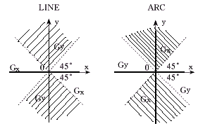
Where B is the separator. XY and YY: 1 When machining a straight line, it is the end point coordinate of the line (the origin is at the starting point of the line); 2 When the arc is machined, it is the starting point coordinate (the origin is at the center of the arc). J and G: G is the counting direction. There are two directions of X and Y, which are G x and G y respectively . As shown in Figure 1, for a straight line, when the line is in the shaded area, G takes G y , otherwise G takes G x ; If the end point of the circle is in the shadow area, G takes G x , otherwise it takes G y . J is the sum of the projection line length or projection length of the machining path (straight line or arc) in the counting direction; Z is the machining instruction, there are 12 kinds (Figure 2).
1.2 Auto CAD entity selection set and entity group code
In AutoCAD, each graphic element can be treated as a separate entity, and the ssget() function can be used to construct the required entity selection set. The data of each entity can be obtained by looking up its entity group code. Each entity has an entity name, represented by a group code of -1, and an entity type, such as Line, Arc, Pline, etc., represented by a group code of 0, and other group code relationships are shown in the following table.

Figure 1 Counting direction selection (left is a straight line, right is an arc)

Figure 2 Schematic diagram of the machining instructions (left is a straight line, right is an arc)
Next page
October 14, 2024
September 27, 2024
この仕入先にメール

Privacy statement: Your privacy is very important to Us. Our company promises not to disclose your personal information to any external company with out your explicit permission.

Fill in more information so that we can get in touch with you faster
Privacy statement: Your privacy is very important to Us. Our company promises not to disclose your personal information to any external company with out your explicit permission.