Privacy statement: Your privacy is very important to Us. Our company promises not to disclose your personal information to any external company with out your explicit permission.
In mechanical products, the eccentric sleeve acts to adjust the center distance of the gear pair, and the transmission precision of the gear pair is adjusted by adjusting the eccentric sleeve. The surface roughness of the eccentric sleeve machining, the dimensional accuracy of the eccentricity, and the dimensional accuracy of the eccentric groove directly affect the transmission accuracy of the gear pair, which in turn affects the transmission effect, the service life of the gear and the torque transmitted. Therefore, the processing quality of the eccentric sleeve, its uniformity and consistency directly affect the performance of the entire product. The eccentric sleeve is a thin-walled piece that is highly resistant to wear and tear. Through the reasonable process analysis of the eccentric sleeve, CNC milling is selected as the processing method, and the positioning and repeating positioning precision of the CNC milling machine is high. The reasonable and simple machining procedure and the correct path are used to ensure the dimensional accuracy of the eccentric sleeve. And consistency.
1. Structure and process analysis of eccentric sleeve
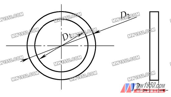
The eccentric sleeve (see Fig. 1, 2) does not coincide with the center of the machined surface to be machined, so the machining allowance is not uniform, the minimum machining allowance is 1.5mm, and the part cannot withstand large torque and cutting force. It brings great difficulty to processing. Therefore, the selection of reasonable processing methods and the correct process flow become the key.

Figure 1 Eccentric sleeve blank drawing

Figure 2 eccentric sleeve parts drawing
(1) Selection of processing methods
From the blank drawing of the eccentric sleeve, it is a thin circular ring member, and the surface to be machined is on the upper surface and the lower surface of the circular ring, and the shape of the machining surface is complicated to be a circular arc connection, and there is a convex groove and a groove, and Evenly distributed on the circumference of 360°. The surface roughness value of the surface to be machined is Ra=3.2 μm, so the milling method is selected.
(2) Choice of clamping method
Since the surface to be machined is located on the upper and lower surfaces of the part, it can only be machined by secondary clamping. There are three ways to set up:
1 Press-down type, that is, the threaded mandrel is positioned with the middle hole, and then the pressure plate is prepared by the nut. Although this method restricts the movement of the parts in the X, Y, and Z directions, since the mandrel and the inner hole of the workpiece are gap-fitted, the downward pressure of the pressure plate is only used to prevent the workpiece from rotating in the X and Y planes. It is easy to cause the workpiece to rotate during the process, resulting in waste. The platen should also be eccentric, but because the position is not fixed, it is easy to mill to the platen during processing. In this way, the mandrel needs to be made, the production cycle is long, and the processing cost is increased.
2 external clip type, using the three-claw self-centering chuck of the car to process the outer circle of the workpiece. However, the thickness of the workpiece is too thin, only 13mm, and the thickness used for clamping is only 9mm. The clamping area is too small, and it is easy to rotate during processing. In the process, the tool is easy to hit the chuck, and the knife is generated. .
3 inner top type, adopting the three-jaw self-centering chuck for the vehicle, but the three-claw reverse mounting of the chuck is positioned by the inner hole of the workpiece, and the clamping force is outward. This type of clamping avoids the problem that the cutting force is easy to cause the workpiece to rotate and the tool to hit the jig due to the small clamping area. Therefore, the inner top type clamping method is used for processing in production.
(3) Selection of processing sequence The reasonable processing sequence can effectively control the deformation of the workpiece and control the dimensional accuracy of the workpiece. The excess machining allowance should be removed during processing. Therefore, when processing the workpiece, the principle of “first coarse and then fine” and “first shape and rear hole” should be followed. Then, the machining process for the eccentric sleeve is as follows: clamping the workpiece → milling the outer circle → rough milling the boss → Finishing the boss → drilling center hole → drilling → scribing → re-clamping → milling D2 circle → rough milling 5.5mm slot → finishing milling 5.5mm slot.
Next page
November 18, 2024
November 11, 2024
この仕入先にメール
November 18, 2024
November 11, 2024

Privacy statement: Your privacy is very important to Us. Our company promises not to disclose your personal information to any external company with out your explicit permission.

Fill in more information so that we can get in touch with you faster
Privacy statement: Your privacy is very important to Us. Our company promises not to disclose your personal information to any external company with out your explicit permission.